TaskCam 3D-printed
Specifications:
Camera Dimensions 124 x 50 x 107mm
Image Resolution 1024 x 768pixel
Contents
Overview
List of Components
Making
How to use
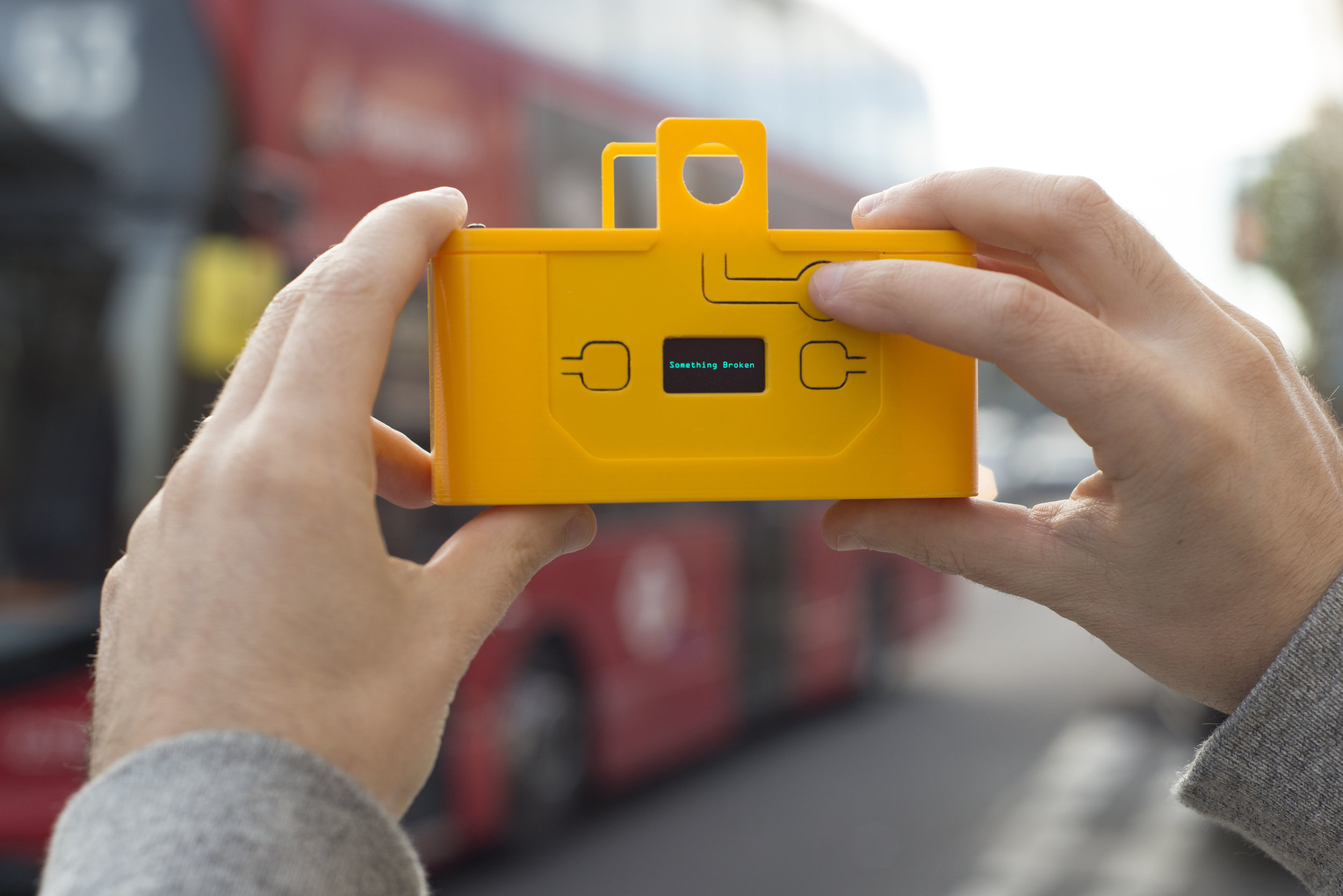
TaskCams recreate the proven Cultural Probe technique of relabelling disposable cameras with requests for pictures. The 3D Printed TaskCam is the basic workhorse of the collection, robust and flexible enough to use across multiple studies.
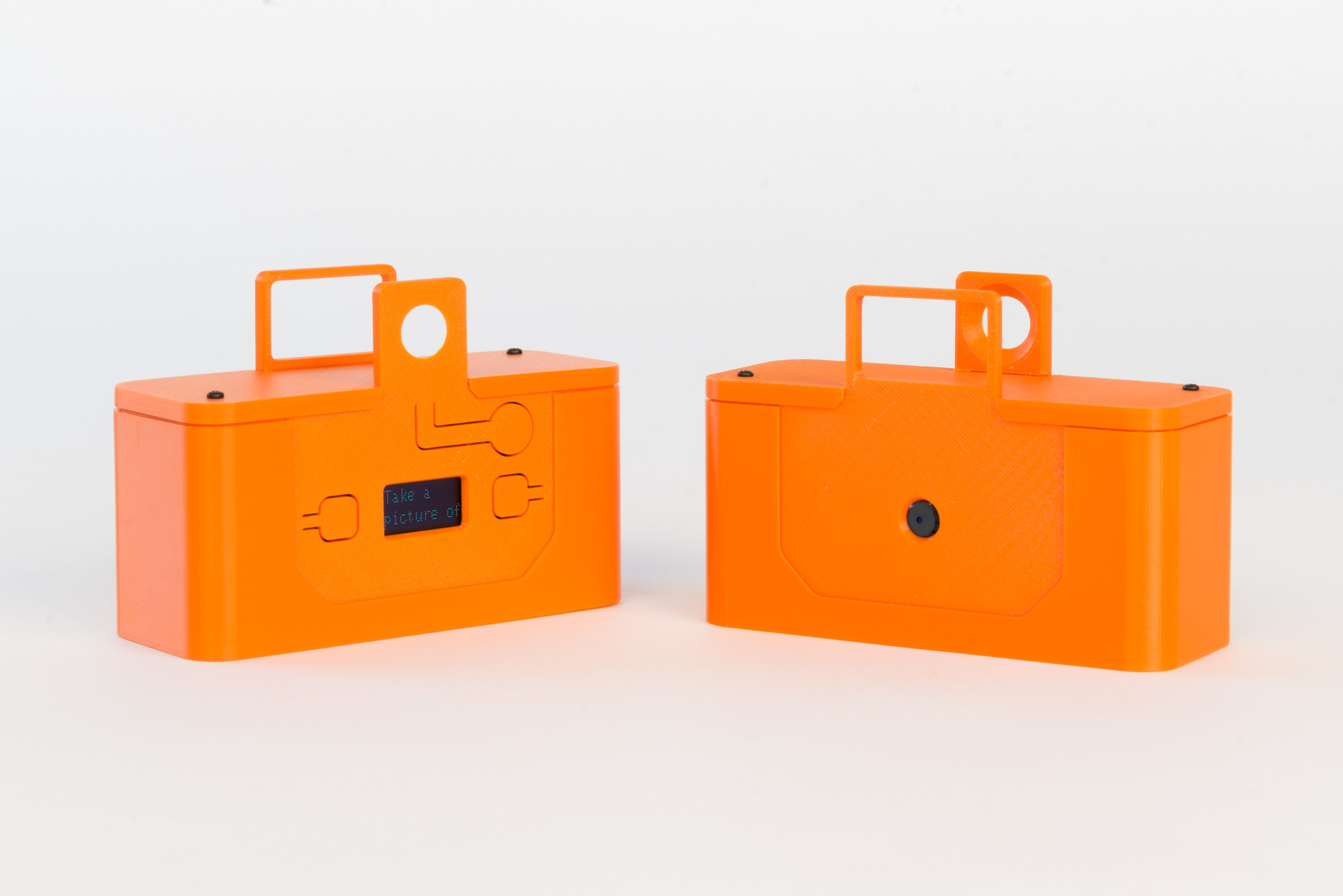
The 3D Printed TaskCam has a small screen on the back that shows a scrollable list of requests for pictures. Researchers can load their own list of requests onto the camera to prepare for a study. When users take a picture, the image is tagged with the current request, and stored on a standard flash drive that can be removed for downloading.
The casing for the 3D Printed TaskCam can be printed successfully without support materials even on low-end printers. The device requires a custom Arduino shield, which you can buy online at cost price, or make yourself using open-source plans we provide. Smart power management mean that two AA batteries provide more than enough power for an entire user study.
List of all the components to assemble the TaskCam
TaskCam Arduino shield available here
Arduino Uno or compatible
3D printed case (download files below)
Micro SD card
2 x AA batteries
2 x No.2 6.4mm self-tapping screws available here
Camera and battery leads (supplied with the TaskCam Arduino shield)
Software
List of handy equipment
Small Phillips screwdriver (cross head)
3D printer
Download 3D files to make the case
.stl files (for direct 3D printing) and .step (editable assembly) files
to view and download various file formats
3D-printed TaskCam 2, Fusion360
Making
Step 1 Program the Arduino Uno following instructions here.
Step 2 Separate the battery and camera modules from the shield using side cutters. Also remove and put aside the small board next to the battery board marked ‘Ext Switch’ as it is not used in this version.
Step 3 File the cut tabs of each module smooth.
Step 4 Solder battery leads to the board observing the correct polarity.
Step 5 Connect the battery lead into the battery socket on the main board.
Step 6 Connect the camera lead into the camera header on the main board, observing the orientation in the photograph above.
Step 7 Connect the camera lead into the camera header on the camera module, observing the orientation in the photograph above.
Step 8 Your camera needs some questions. For advice on how to write good Probe questions, please read here. Insert the micro SD card into your computer. Write your questions in the text box below, giving each question a new line. Once you're done, click "Download probe questions file". Your browser will download a file called "q.txt". Place that file into the SD card. Eject it and unplug it from your computer.
Please note: if you have downloaded the file before, your file might be called q(1).txt and needs to be changed to q.txt for the TaskCam software to recognise the file.
Step 9 Insert the Micro SD Card.
Step 10 Insert two AA batteries.


Step 11 Insert Arduino Uno into the main board, taking care to pass the camera lead between the two.
Step 12 Slide the battery module into the the lower shell of the case. Note that a thin tab at the side of the case will slide between that batteries.
Step 13 Slide the main board and Arduino into the the lower shell of the case*.
Whoops! We have photographed the main board sliding in upside down. The word 'shield' printed on the board should be at the top. Thanks to Sören for spotting this error.


Step 14 Slide the camera module into the the lower shell of the case, taking care with the camera and battery leads. Make sure that the battery board does not touch the other boards, if in doubt, add some electrical tape to the rear of the battery board.
Step 15 Slide the front section of the camera into the lower shell.
Step 16 Slide the rear section of the camera into the lower shell.
Step 17 Place the top section of the camera into the lower shell, taking care to locate the front and rear sections into their slot. If the top does not fit nicely, check the the tabs on the Taskcam Arduino shield are cleanly filed down. If it still does not fit, take a look at the slots inside of the case to see if they are obstructing any of the boards. Due to minor variations in 3D printing, some fettling may be required.
Step 18 Use two No.2 6.4mm self-tapping screws to secure the case (note that these are not the same as the M3 machine screens supplied with the TaskCam Arduino Shield).
Step 19 Switch on the camera on by pressing and holding the shutter / power button.
How to use
Turn camera on by pressing and holding the shutter / power button.
Select a task with the left and right button next to the display.
Use the viewfinder to frame your picture, press the shutter button to take a picture that answers the task. The display graphic changes when a picture is taken.
Select your next task.
The camera with switch off automatically or by pressing and holding the shutter / power button.