TaskCam Paper
Right-handed Version
Specifications:
Camera Dimensions 113.5 x 41.5 x 60mm
Image resolution 1024 x 768pixel
Contents
Overview
List of Components
Making
How to use
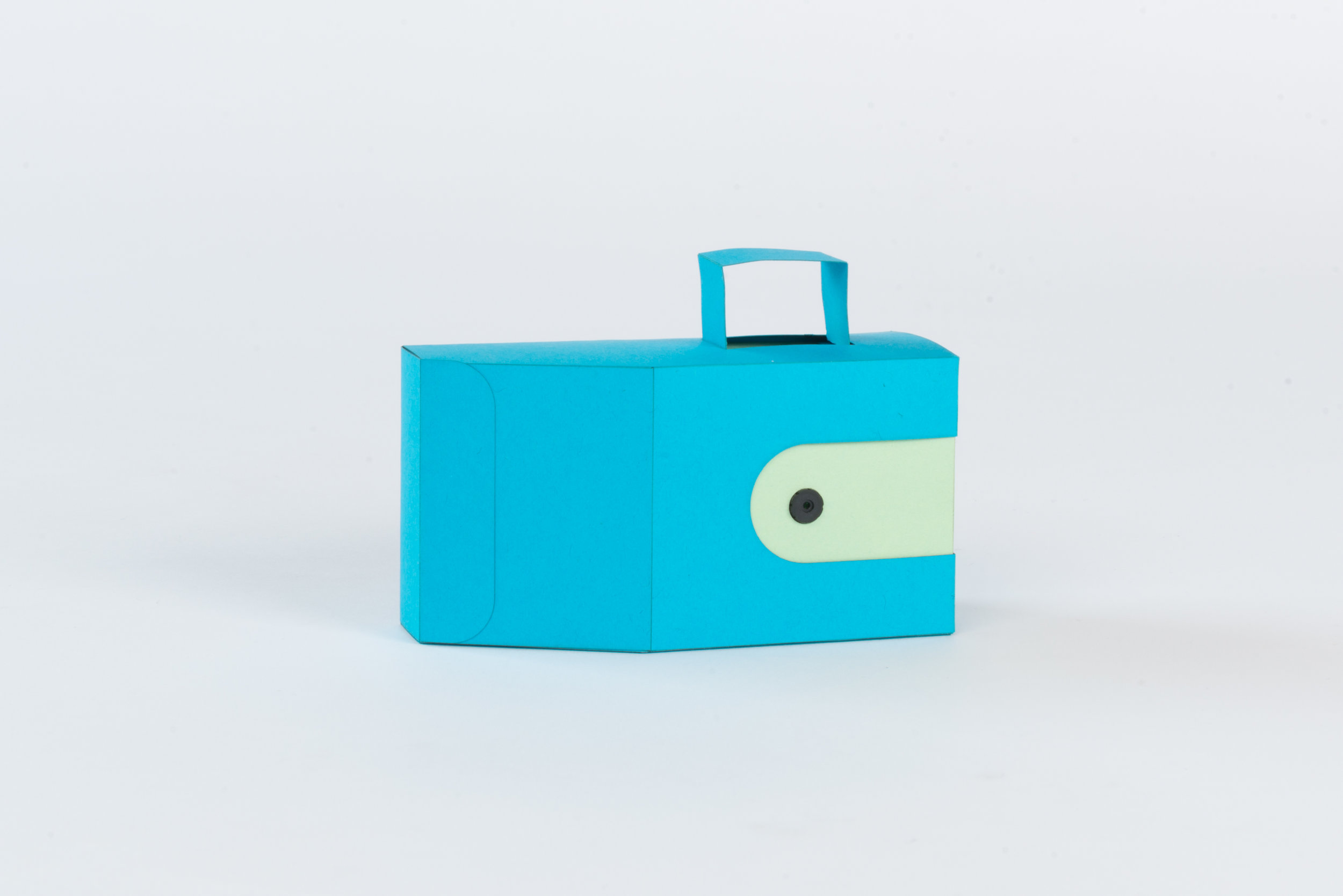
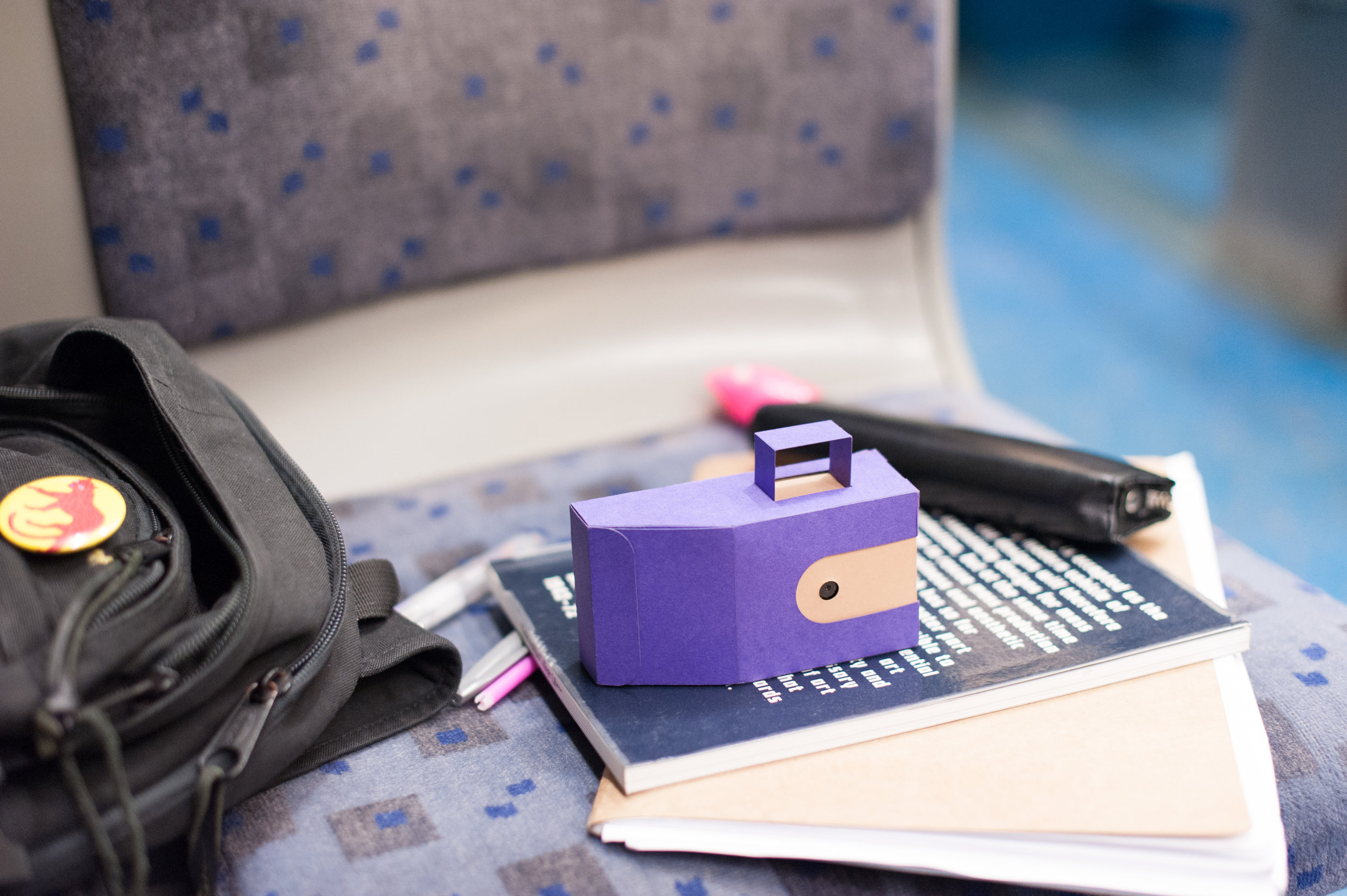
TaskCams recreate the proven Cultural Probe technique of relabelling disposable cameras with requests for pictures. The Paper TaskCam is housed in a casing made from paper or light card, allowing it to appear as playful or elegant as required. TaskCam Paper is available in both left and right-handed configurations.
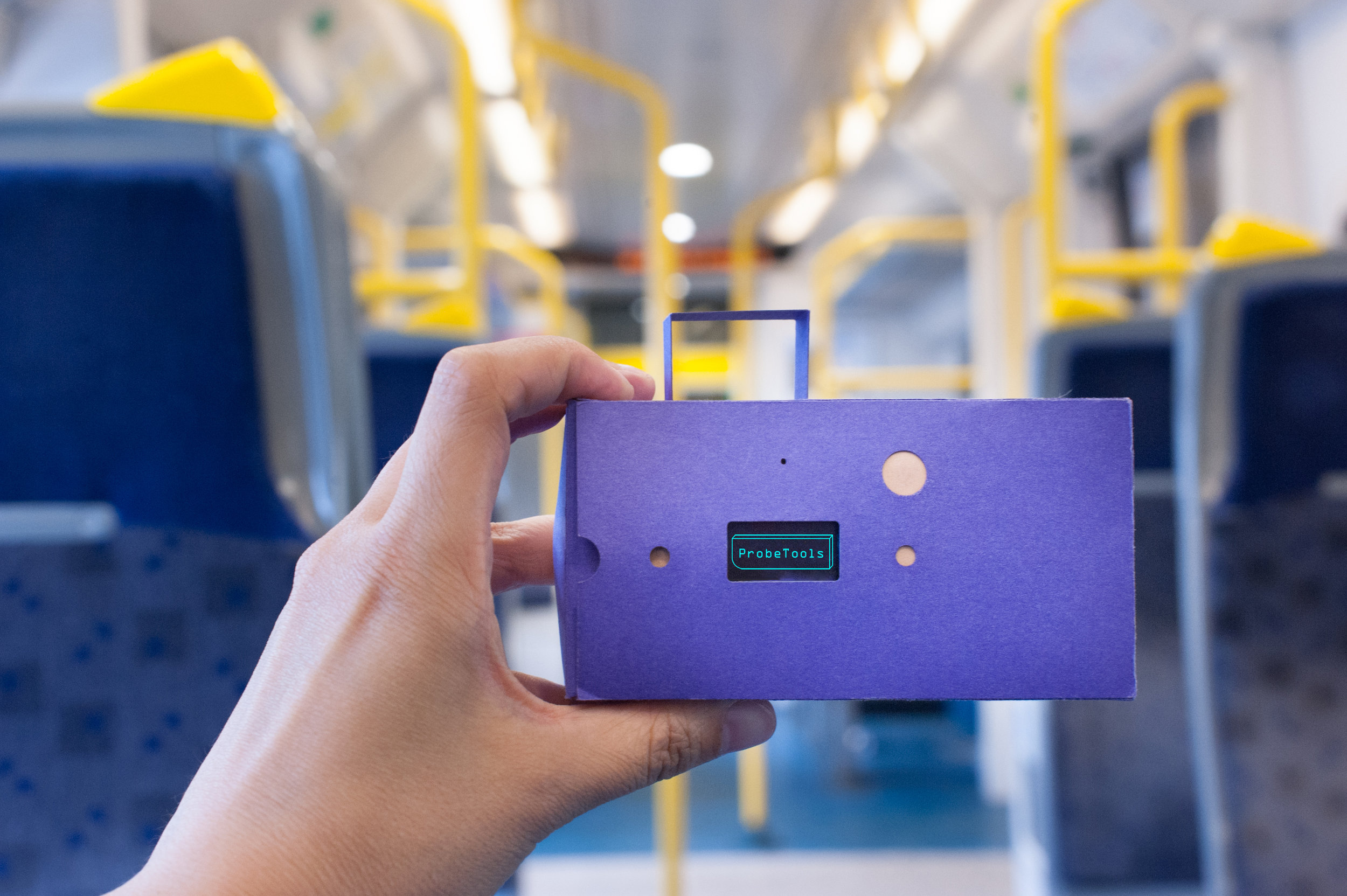
The Paper TaskCam has a small screen on the back that shows a scrollable list of requests for pictures. Researchers can load their own list of requests onto the camera to prepare for a study. When users take a picture, the image is tagged with the current request, and stored on a standard flash drive that can be removed for downloading.
The casing for the Paper TaskCam is constructed from two A4 sheets of card or paper, cut out according to the template we provide. he device requires a custom Arduino shield, which you can buy online at cost price, or make yourself using open-source plans we provide. Smart power management means that two AA batteries provide more than enough power for an entire user study.
List of all the components to assemble the TaskCam
TaskCam Arduino shield available here
Arduino Uno or compatible
2 sheets of A4 paper or card (270 gsm) to lasercut or cut by hand
Micro SD card
2 x AA batteries
2 x M3 10mm machine screws (supplied with the TaskCam Arduino shield)
2 x M3 nuts (supplied with the TaskCam Arduino shield)
2 x M3 Nylon Standoffs 10mm (supplied with the TaskCam Arduino shield)
1 x M3 Nylon nut (supplied with the TaskCam Arduino shield)
Camera leads (supplied with the TaskCam Arduino shield)
Software
List of handy equipment
Lasercutter or paper cutting scalpel and rule
Small Phillips screwdriver (cross head)
Small Phillips screwdriver (flat head)
Double-sided tape or glue
Side cutters
Metal File
Micro SD card reader
Download files to make the case
Making

Step 1 Program the Arduino Uno following instructions here.
Step 2 Separate the battery module from the shield using side cutters. Also remove and put aside the small board next to the battery board marked ‘Ext Switch’ as it is not used in this version.
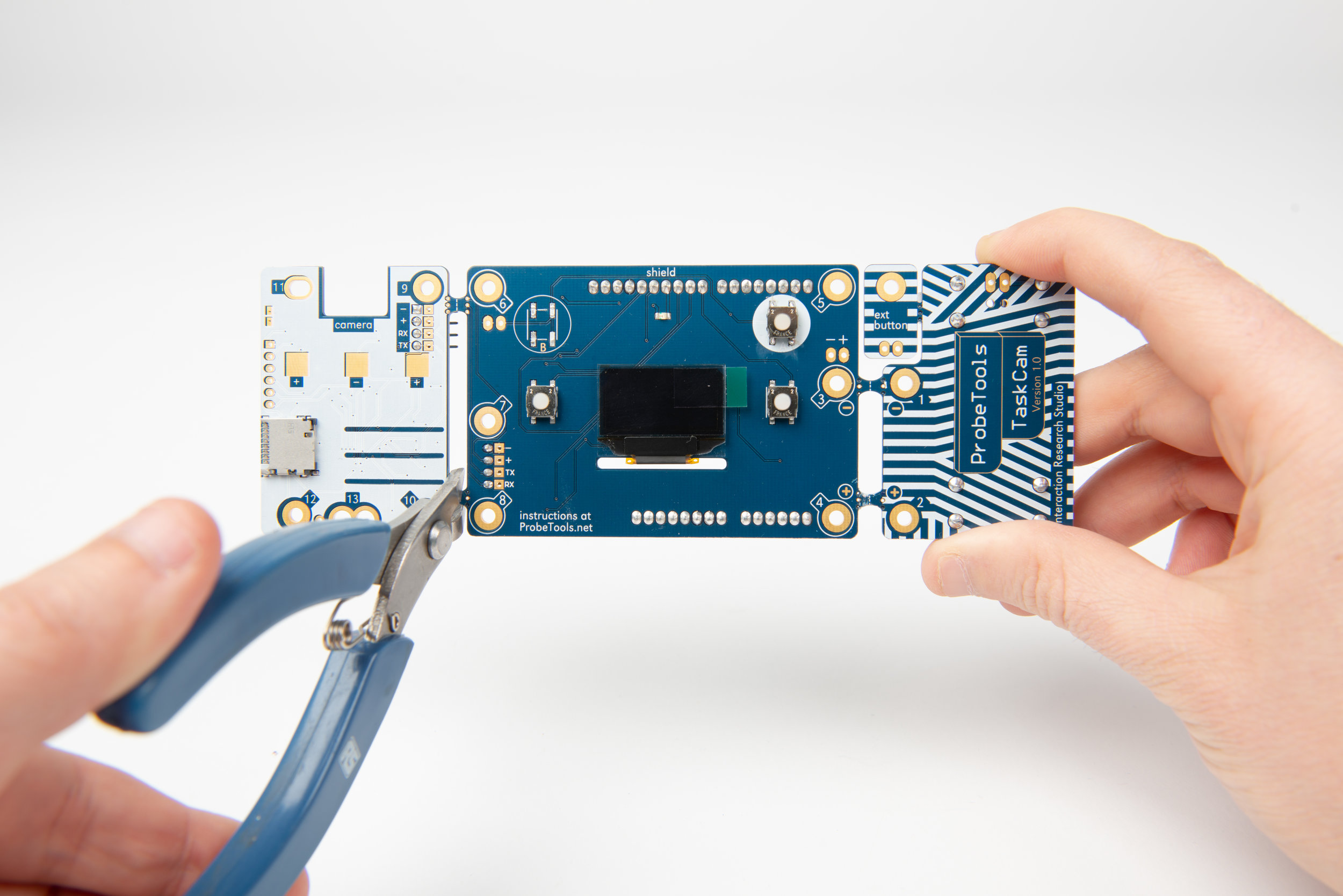
Step 3 Separate the camera module from the shield using side cutters.

Step 4 File the cut tabs of the battery module smooth.

Step 5 File the cut tabs of the camera module smooth.

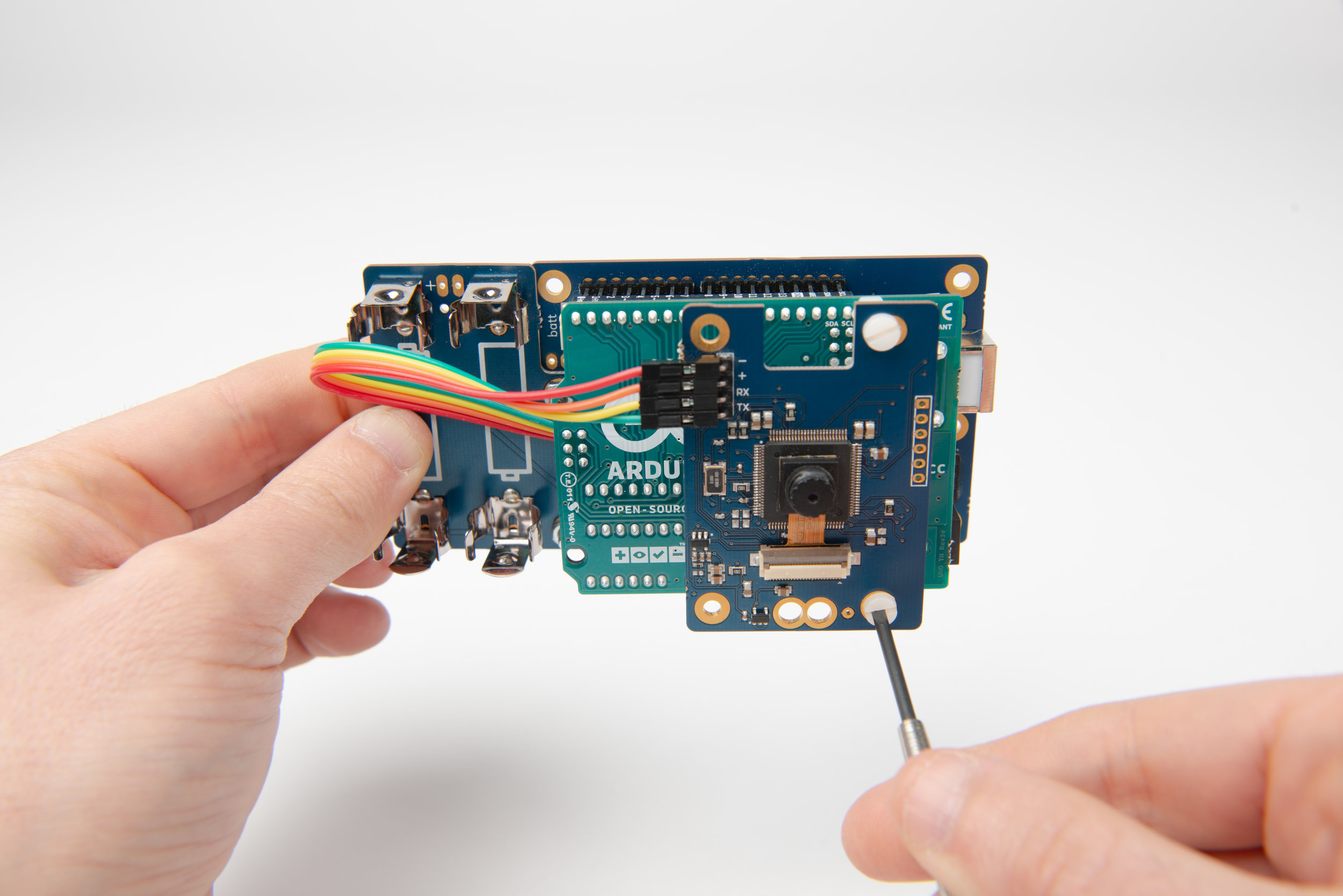
Step 6 Connect the camera lead into the camera header on the main board, observing the orientation in the photograph above.
Step 7 Connect the camera lead into the camera header on the camera module, observing the orientation in the photograph above.
Step 8 Attach the battery board to the main board using machine two screws. (fixings supplied with the Arduino Shield)

Step 9 Secure the battery board to the main board using two nuts. (fixings supplied with the Arduino Shield)

Step 10 Join the Arduino Uno to the camera module by first attaching one nlyon standoff to Arduino board with a nylon nut. (fixings supplied with the Arduino Shield)
Step 11 Screw the camera module into the standoffs with a nylon screw. (fixings supplied with the Arduino Shield)

Step 12 Insert the header pins of the main/battery board combination onto the header sockets of the Arduino.
Step 13 Screw the camera module into the lower standoff with a nylon screw. Locate the upper stand-off of the camera board in the corresponding hole on the Arduino, but do not add a nut. (fixings supplied with the Arduino Shield)

Step 14 Your camera needs some questions. For advice on how to write good Probe questions, please read here. Insert the micro SD card into your computer. Write your questions in the text box below, giving each question a new line. Once you're done, click "Download questions file". Your browser will download a file called "q.txt". Place that file into the SD card. Eject it and unplug it from your computer.

Step 15 Insert the SD card into the SD card holder on the camera module.
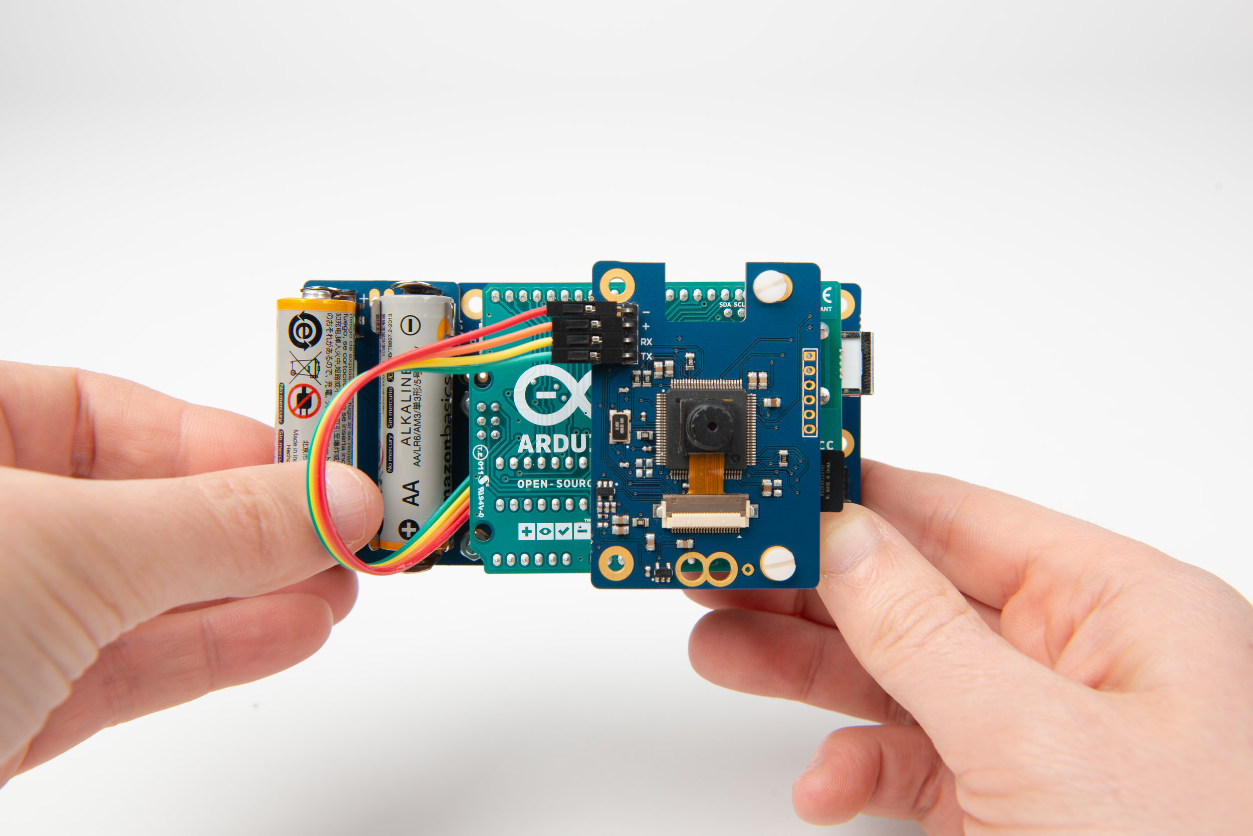
Step 16 Insert two AA batteries into the battery holders.

Step 17 At this stage you can check that your camera is working by switching it on with the top right power button.
Step 18 Apply double-sided tape or glue to all the tabs on the cut card of the outer case.
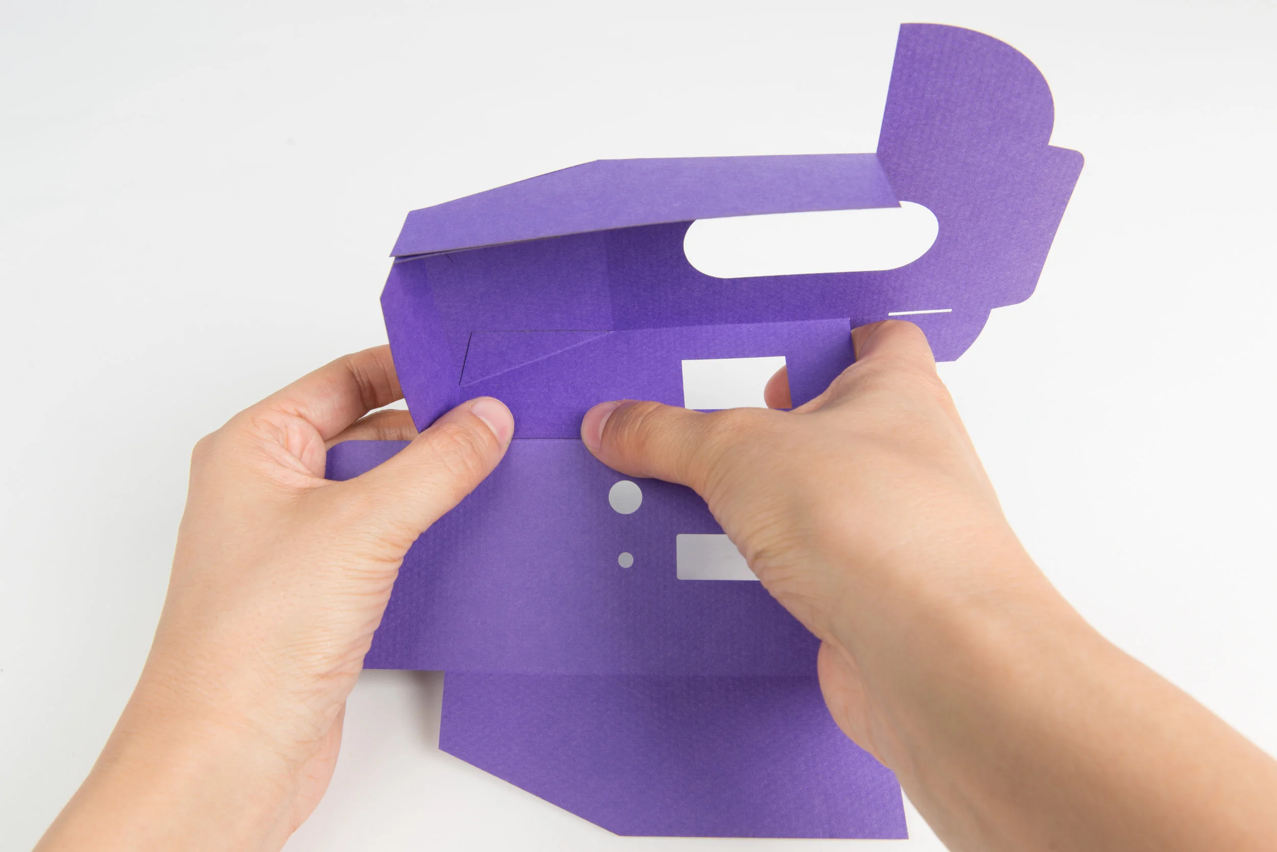
Step 19 Fold all engraved lines of the case, to beginning forming the shape of the outer case.


Step 20 Progressively begin to stick tabs in place as shown in the following sequence of photographs.

Step 21 Tape down the edge of this tab fully to allow the inner case to smoothly slide inside the outer case.


Step 22 Stick the last tab in place, taking care to leave the flap shown at the bottom of this photo open, as this is the door to slide in the inner case later.
Step 23 Apply double-sided tape or glue to all the tabs on the cut card of the inner case.
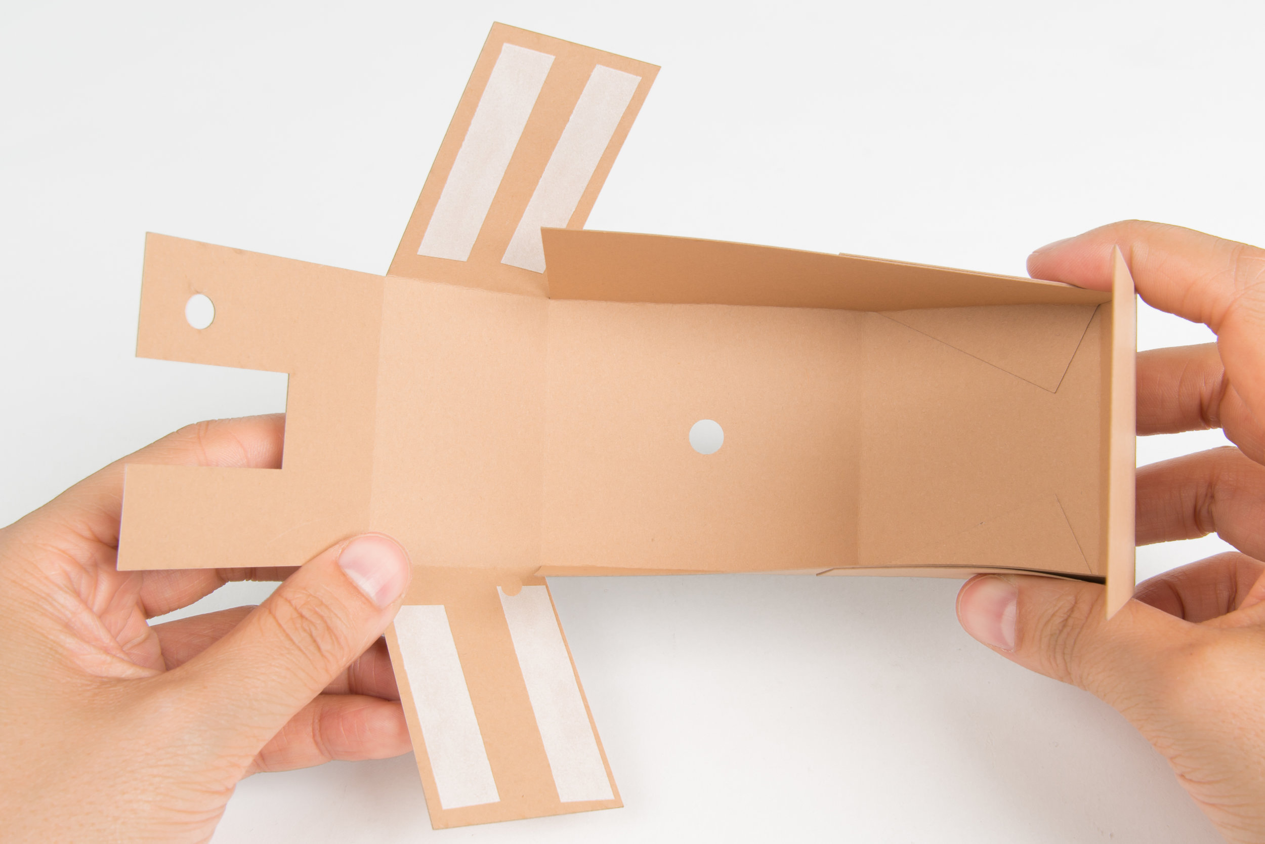
Step 24 Fold all engraved lines of the case, to beginning forming the shape of the inner case.


Step 25 Progressively begin to stick tabs in place as shown in the following sequence of photographs.


Step 26 Place the camera electronics in the inner case as shown, and close the flaps.
Step 27 Take the fully assembled inner case and slide into the outer case as shown in the following sequence of photographs, not forgetting to fold and insert the viewfinder.


Step 28 The TaskCam paper is ready to use.
How to use
Turn camera on by pressing and holding the shutter / power button.
Select a task with the left and right button next to the display.
Use the viewfinder to frame your picture, press the shutter button to take a picture that answers the task. The display graphic changes when a picture is taken.
Select your next task.
The camera will switch off automatically or by pressing and holding the shutter / power button.