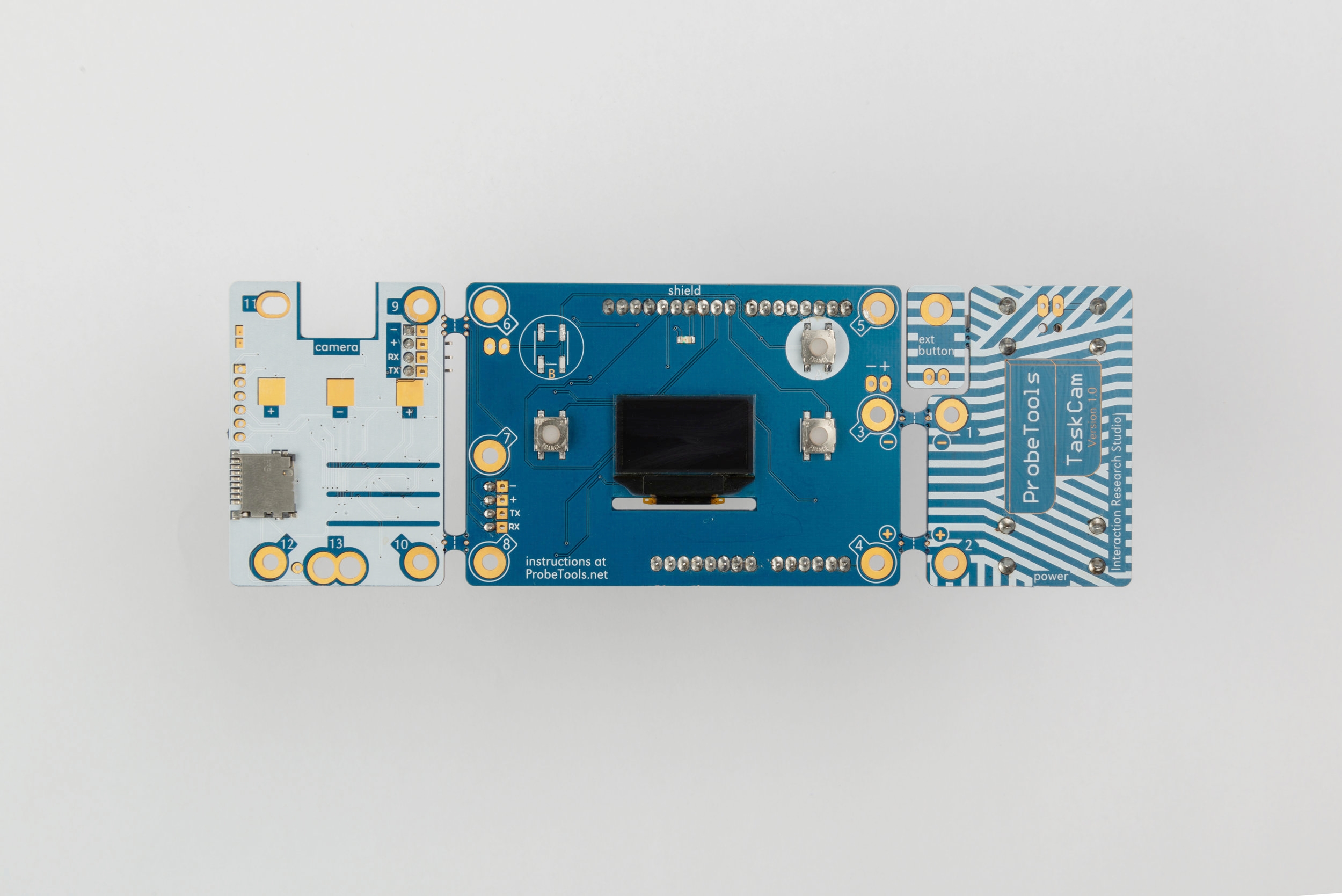
TaskCam Arduino Shield
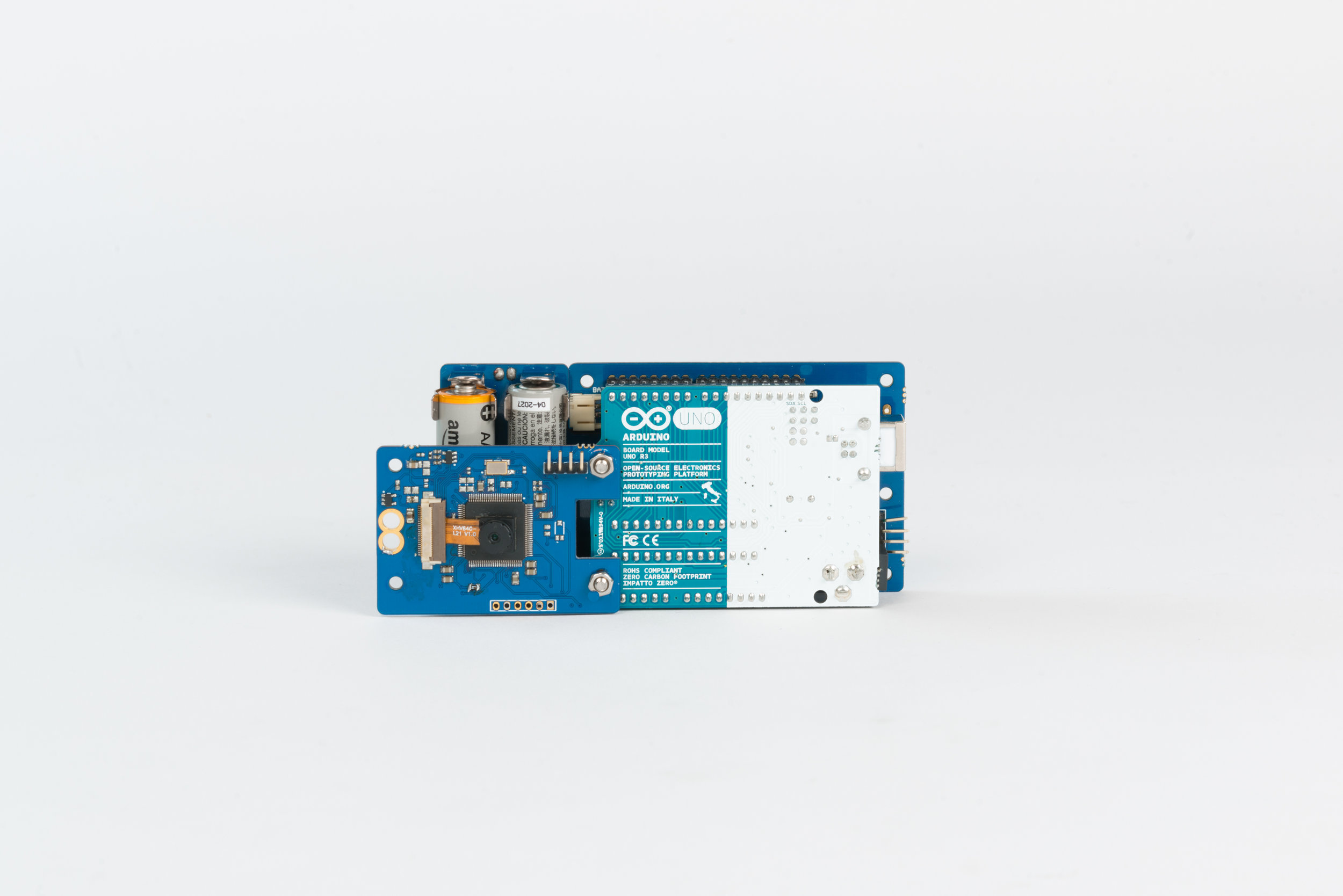
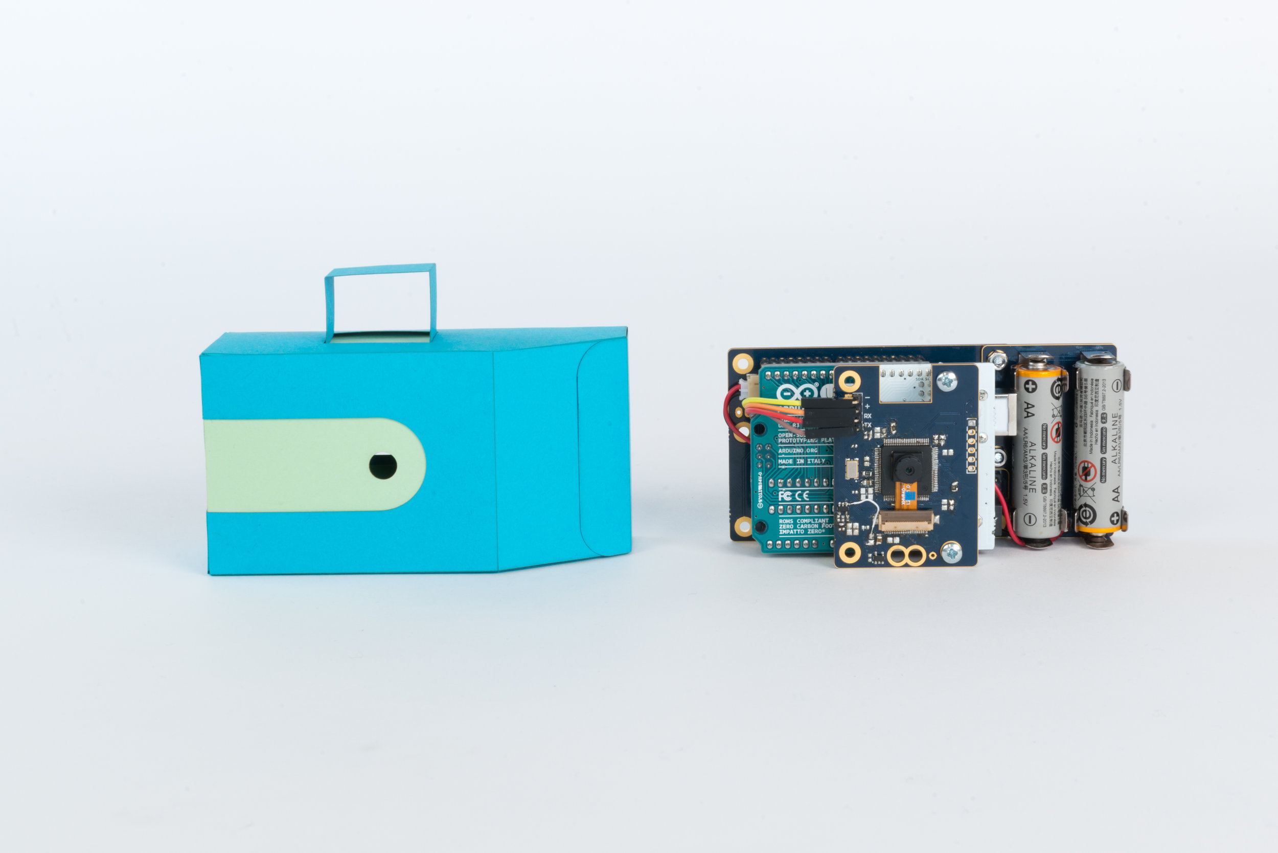
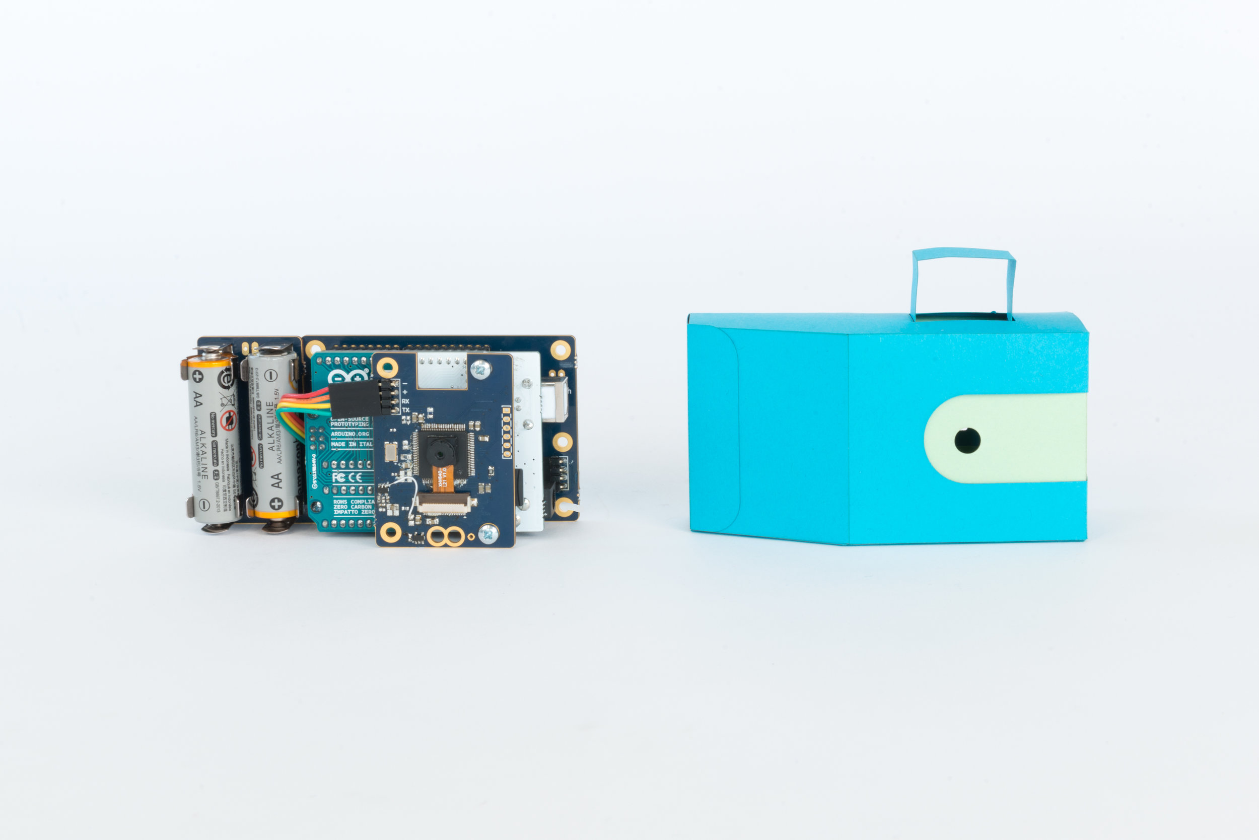
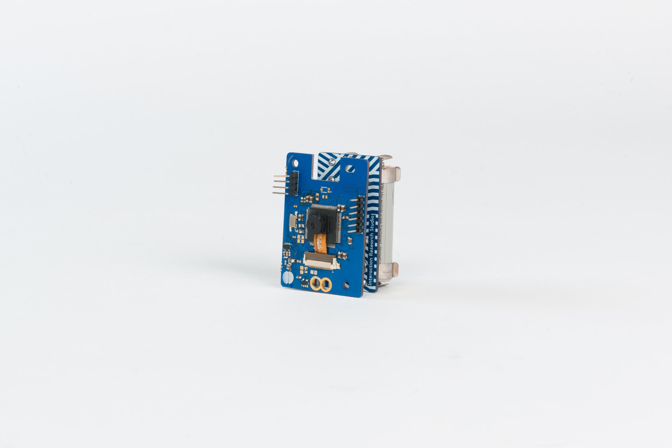
TaskCams are built on a custom Arduino shield designed for the ProbeTools project. A fully functioning TaskCam can be assembled simply by plugging an Arduino microprocessor into the PCB and inserting 2 AA batteries and a micro SD card. The resulting camera can be packaged for immediate use. Alternatively, the PCB, which is perforated and predrilled, can be snapped apart and reconfigured in about a dozen ways (including a matchbox-sized screenless version) without soldering. This allows TaskCams to be constructed in a variety of forms chosen for their affordances or aesthetic qualities.
Purchase: Buy a TaskCam Arduino Shield at cost price from our shop
Make: The TaskCam Arduino Shield is open source, click here for Circuit Maker files
Software: Download Arduino software here
Technical Description
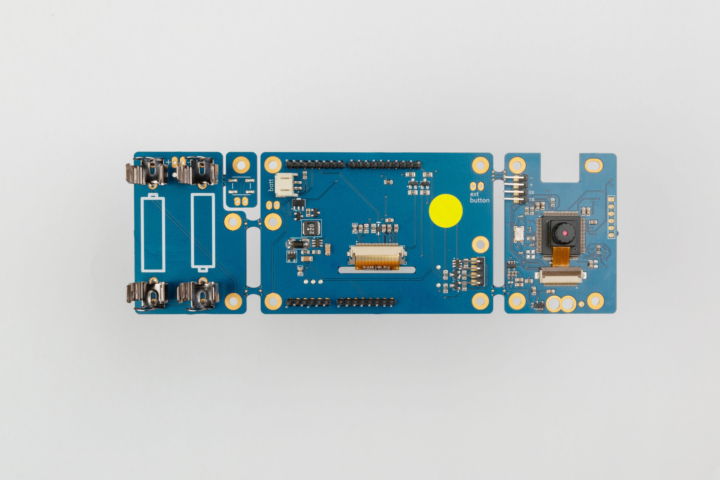
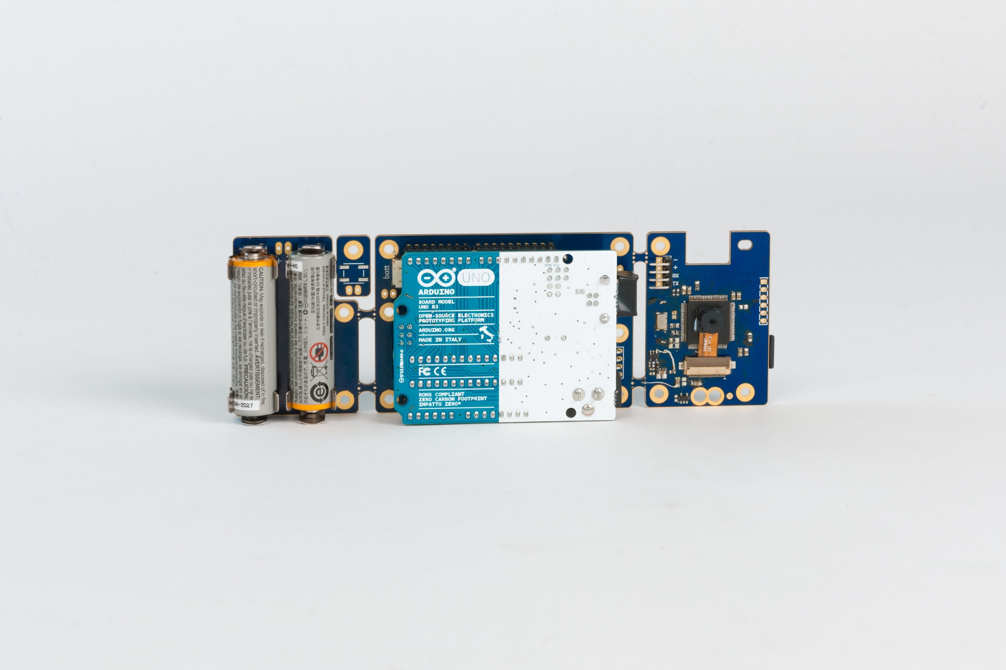
The TaskCam Arduino Shield is made up of three sections: Power, Image Processing and User Interface. Each of these sections are connected through internal connections on the Printed Circuit Board, but also have header pins and plated drill holes with the relevant connections for when the boards have been separated. The system is powered from two AA batteries, with the resulting voltage boosted to 5v using a High Efficiency Step up converter. This is then used to power the Arduino Uno board and also regulated to 3.3v for the remaining peripherals on the PCB that require 3.3v Logic.
The Arduino is used to control the system, using I2C protocol to communicate with the 128x64 pixel OLED display and Serial UART to instruct the Camera MCU to perform tasks. Both of these protocols require 3.3v level shifting to work without risk of damage to parts. The system also contains a soft-latching circuit, which allows the Arduino to disconnect the input power source from the system when not in use. This allows the circuit to preserve battery life when not in use, and also turn off after an idle period predetermined in the Arduino firmware. The combination of a latching switch and push button within the circuit allows the user to turn on the device when powered down, but also use the button as a user input via a GPIO on the Arduino, like the other push buttons on the board.
The board also uses a High side Mosfet switch to control the power to the Image processing section. This allows the system to preserve battery life when the device does not require image capture. The image processing section is constructed of an ARM Cortex M4 Microcontroller and an Omnivision OV2640 2mp Camera. The higher specification processor is required for the image processing and speed of data handling needed to capture the images (currently 1024x768 pixels). The Microcontroller is also connected to a Micro-SD card socket via SPI connection. This allows the Microcontroller to pass data directly to an Micro SD card for storage. The direct connection between the image processing Microcontroller also this section to work as a standalone device without the need for the User interface section. The direct connection also allows for future updates to the Image processing firmware via an SD card bootloader, if required.