Archive - TaskCam Paper version 1
Various components of the TaskCam Version 1.0 are not manufactured anymore. Go to TaskCam Version 2.0 to build the current TaskCam.
Specifications:
TaskCam Version 1.0 (version 2.0 here)
Camera Dimensions 100 x 38 x 62mm
Image resolution 640 x 480 pixel
TaskCam V1 beta software
TaskCam shield version 1

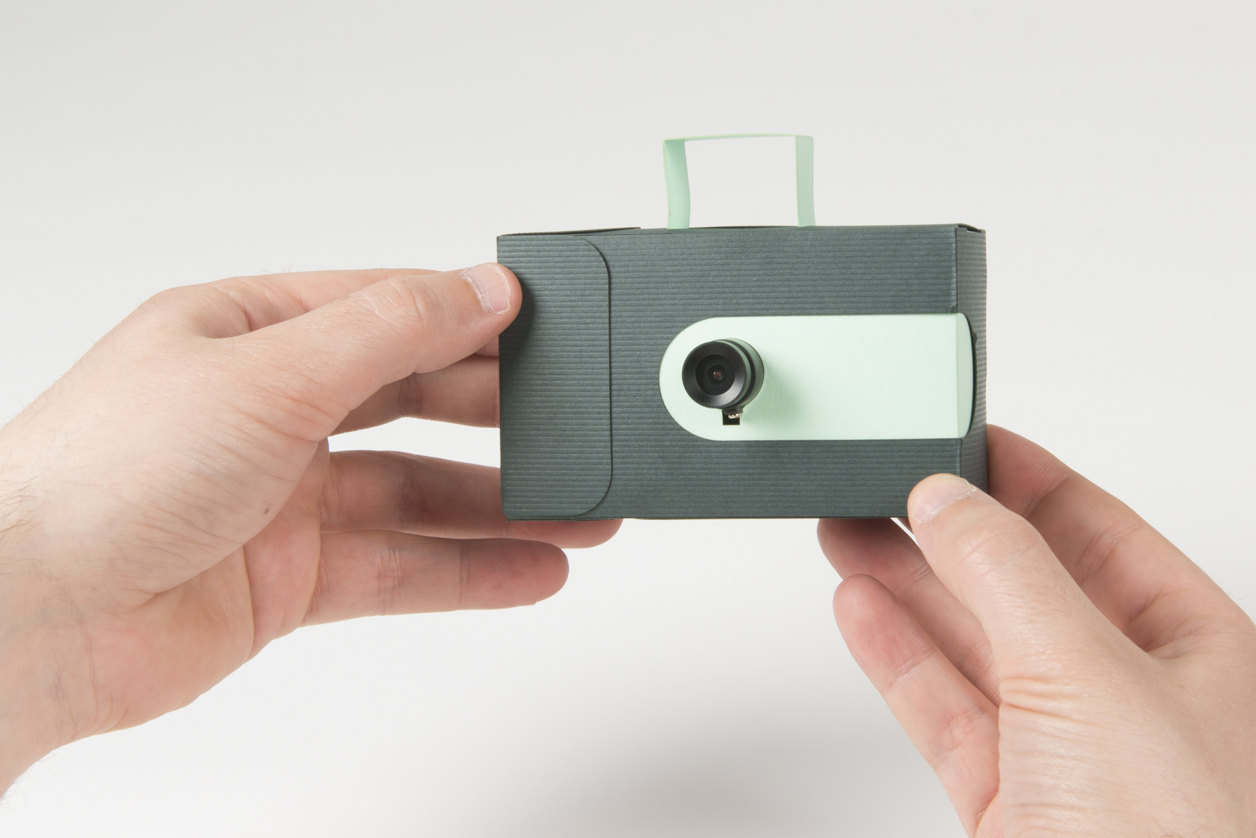
TaskCams recreate the proven Cultural Probe technique of relabelling disposable cameras with requests for pictures. The Paper TaskCam is housed in a casing made from paper or light card, allowing it to appear as playful or elegant as required.
The Paper TaskCam has a small screen on the back that shows a scrollable list of requests for pictures. Researchers can load their own list of requests onto the camera to prepare for a study. When users take a picture, the image is tagged with the current request, and stored on a standard flash drive that can be removed for downloading.
The casing for the Paper TaskCam is constructed from two A4 sheets of card or paper, cut out according to the template we provide. The device requires a custom PCB, based on the Arduino platform, that you can make yourself or buy online. Two AA batteries provide enough power for days or weeks of occasional use.
List of all components to assemble the TaskCam Paper
TaskCam shield version 1
Arduino Uno or compatible
Linksprite JPG Camera
2 sheets of A4 paper or card to lasercut or cut by hand
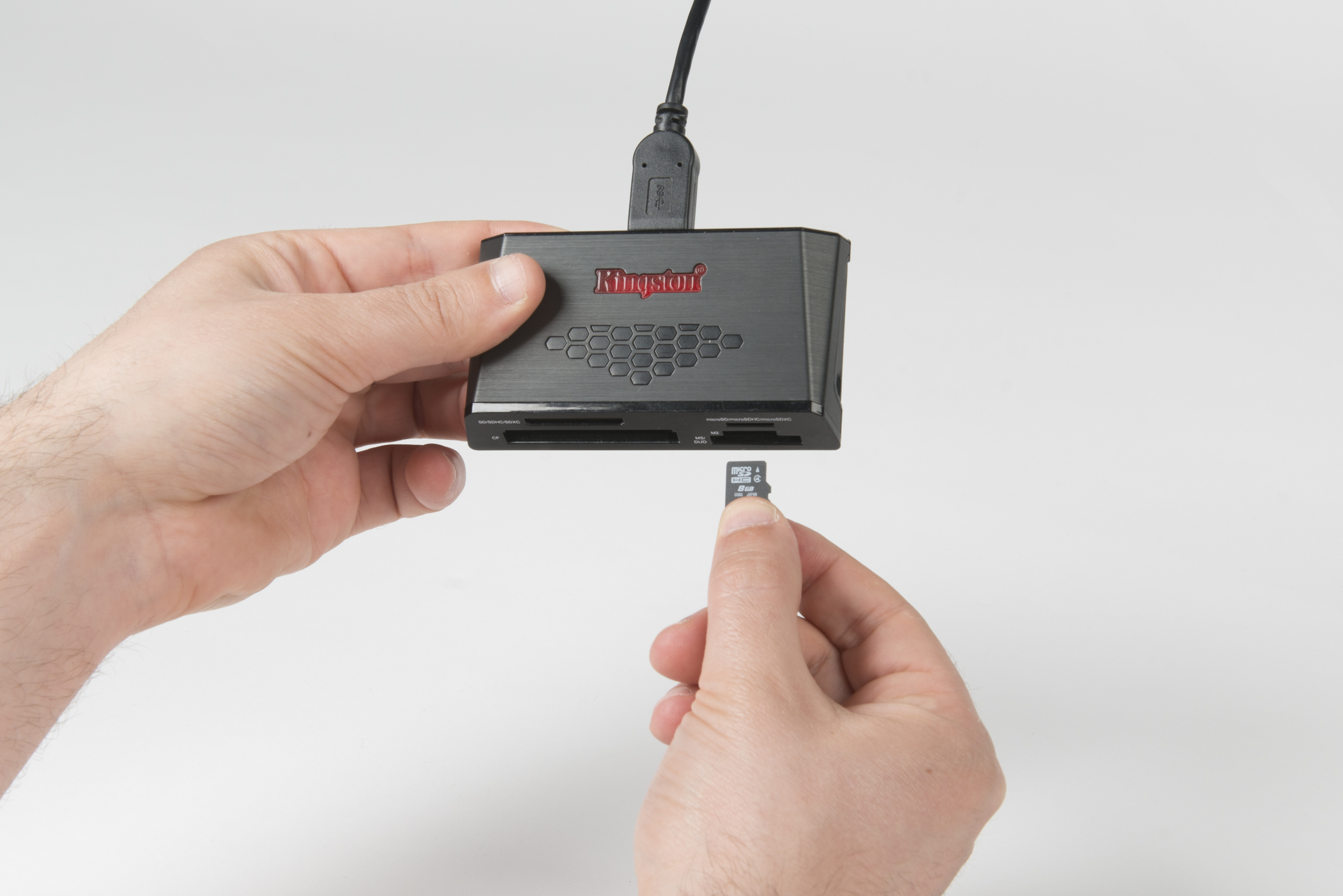
Mini SDcard
Jump wire
AA battery holder
2 x AA batteries
2 x 3D printed button (power button, shutter button)
List of handy equipment
Lasercutter or paper cutting scalpel and rule
Double-sided tape or glue

Step 1 Lasercut or cut by hand the paper components

Step 2 Connect camera module to shield. Make sure to match the order of the cables with the picture. Top to bottom: red, brown, purple, grey. Solder battery leads to the board observing the correct polarity.

Step 3 Plug shield into Arduino. Take care to align the pins with the Arduino’s sockets. Your shield is now ready to use.
Step 4 Your camera needs some questions. For advice on how to write good Probe questions, please read here. Insert the micro SD card into your computer. Write your questions in the text box below, giving each question a new line. Once you're done, click "Download questions file". Your browser will download a file called "q.txt". Place that file into the SD card. Eject it and unplug it from your computer.
Please note: if you have downloaded the file before, your file might be called q(1).txt and needs to be changed to q.txt for the TaskCam software to recognise the file.

Step 5 Slide the 3D-printed shutter onto the shutter button of the shield.

Step 6 Attach the 3-D-printed power button to the shield, the lower part of the button fits into the upper-left hole inside the shield

Step 7 Upload code
Install Arduino on your computer in order to upload the camera program to your Arduino board. Follow Arduino’s guide here. Note that Arduino has a new Web Editor. Please download the Desktop IDE instead.
Once you've installed the Arduino IDE, open it. We now need to download some extra libraries that the TaskCam uses. They’re available from the Library Manager.
Go to Sketch > Include Library > Manage Libraries…
After the Library Manager loads and updates, search for “Adafruit GFX”. The first result will be the Adafruit GFX Library. Go ahead and click on it. Click install.
Now search for “Adafruit SSD1306”. The first result is the Adafruit SSD1306 library. Go ahead and click on it. Click install. You should now have everything you need in your Arduino setup.
Download the code from here. Open the ProbeCam_Arduino.ino file in the folder. This should open the code in the Arduino environment.
We need to make sure that the Arduino program can talk to the board. Plug your Arduino board into your computer with the USB cable.
Go to Tools > Board > Arduino / Genuino Uno. This is the type of board that the camera uses.
We also need to select the right USB port through which we’ll upload the program. Go to Tools > Port. If you’re on Windows, you should be able to see a COM port. If you’re on Mac or Linux, you should be able to see a couple of ports, and one should say Arduino next to it. Go ahead and click on the right port. If you can’t find your Arduino in this menu, refer to Arduino's troubleshooting page.
You’re ready to upload the code to your board! Press the Upload button on the top of your code window (the button next to the tick). After a few seconds, you should see the message “Done uploading.”

Step 6 Plug the micro SD card into the shield. Unplug the Arduino’s USB cable and plug it back in. Once the camera starts up, you should be able to see your questions scroll across the screen.

Step 9 Plug the two AA batteries into the battery holder

Step 10 Make sure you give the camera a thorough test before it goes into its housing. Unplug the USB cable, insert a couple of AA batteries and go through its main functions. Scroll between questions, take a picture, and turn it off and on again with the switch. Once you’re happy that everything works, you’re ready to put the electronics into their housing.

Step 11 Apply double-sided tape or glue to the parts shown in the picture
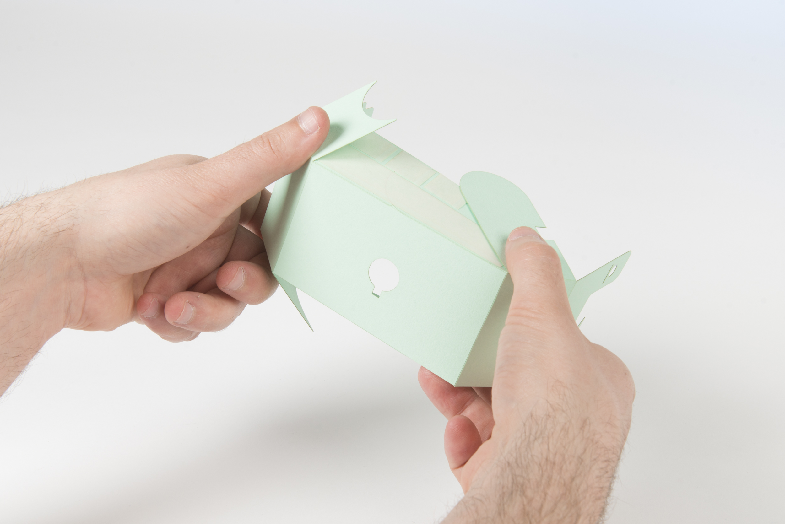
Step 12 Fold all engraved lines of the case, to build the inner case

Step 13 Glue the upper tabs of the sides onto the top of the inner case
Step 14 Glue the lower tabs of the sides to the bottom of the inner case

Step 15 Insert Paper risers aligning to the right side of the inner case

Step 16 Plug the camera through the opening at the front

Step 17 Insert the Arduino with shield and make sure that the power button alines with the opening at the top
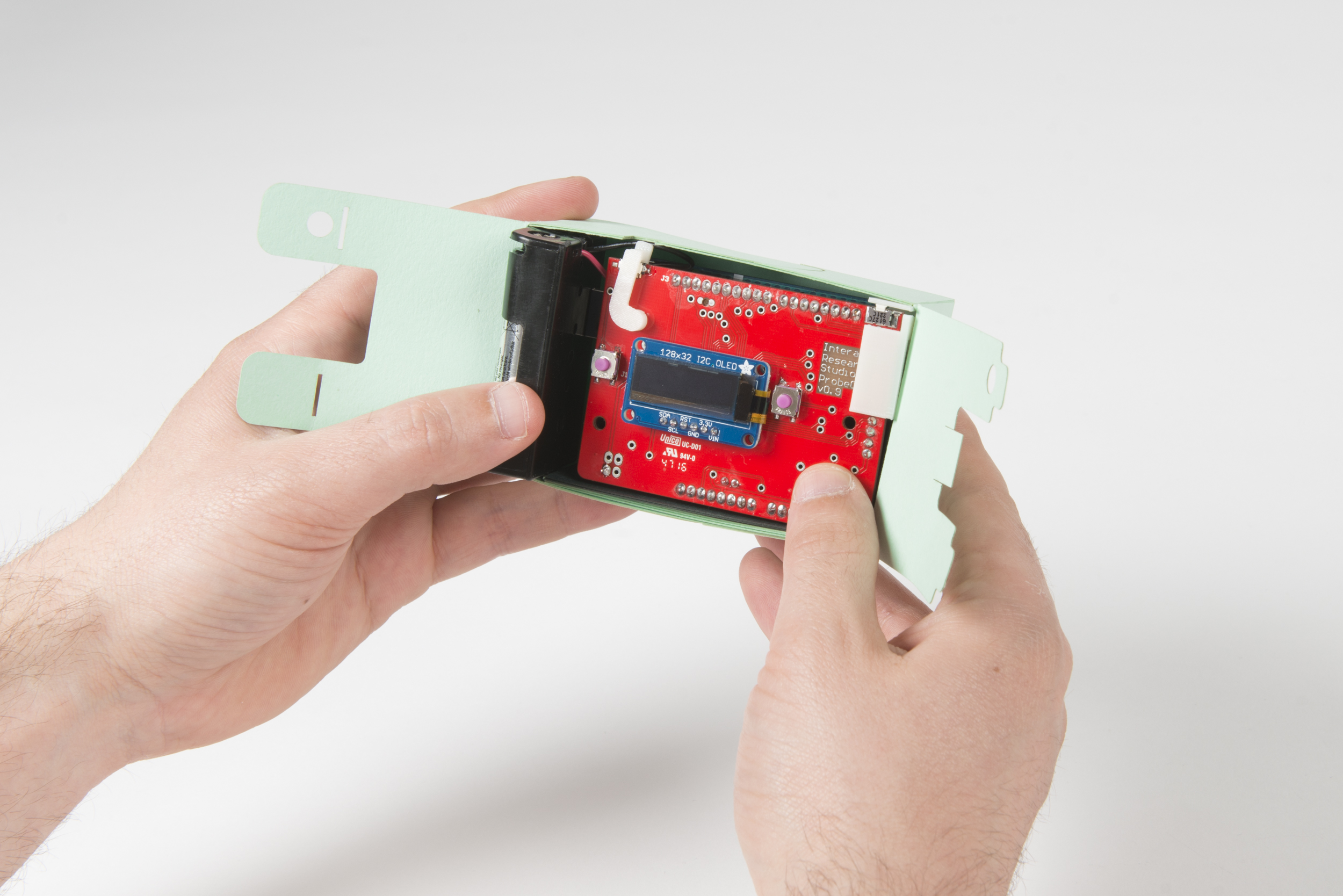
Step 18 Insert the battery holder on the left side next to the shield. The paper risers should bring the shield to the same hight as the battery holder. Adjust adding or removing paper risers until the fit is snug.

Step 19 Close the inner case by interlocking the paper tabs

Step 20 Apply double-sided tape or glue to the parts shown in the picture

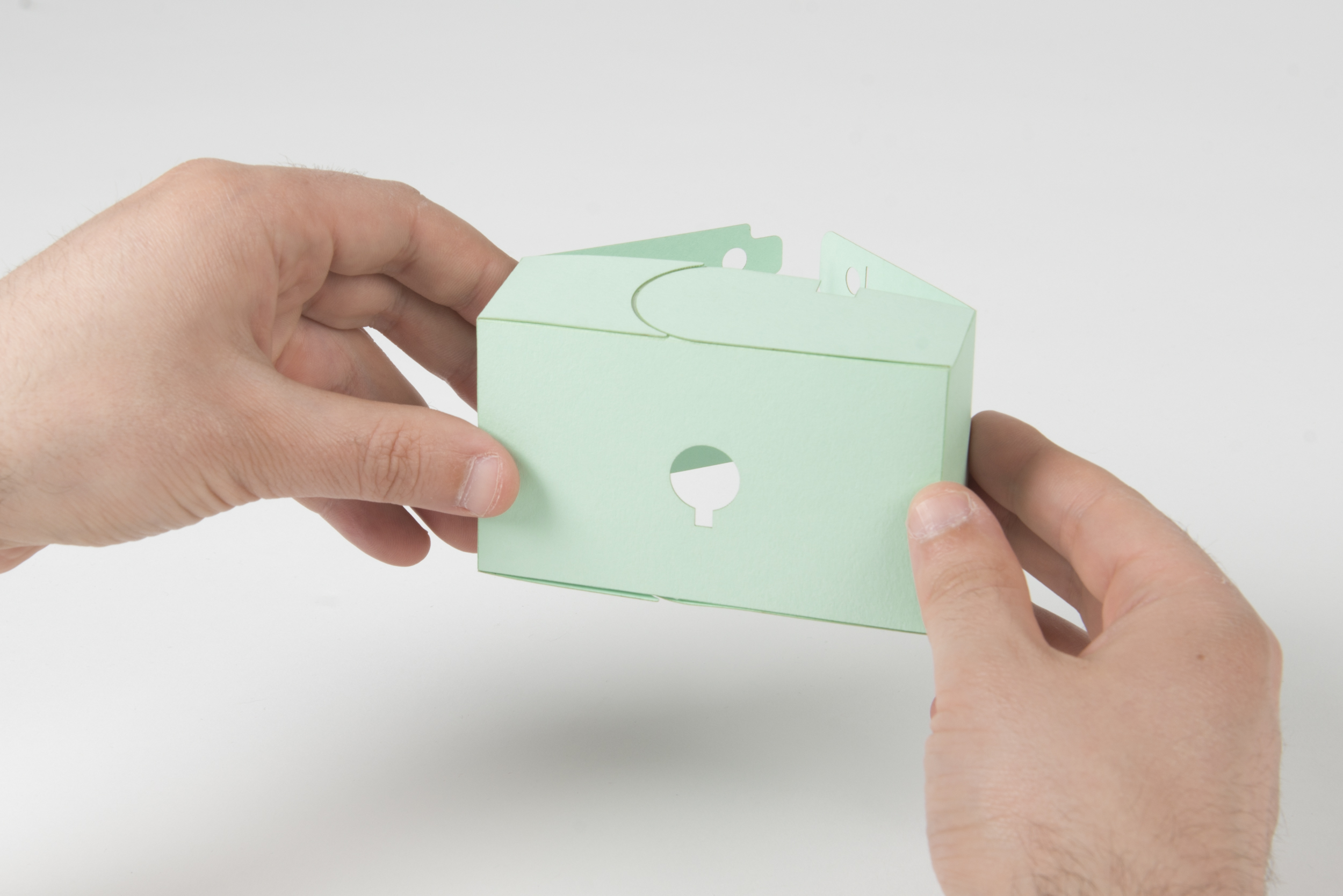
Step 21 Fold all engraved lines of the case, to build the outer case

Step 22 Glue the long tab with the curved side to the bottom of the outer case

Step 23 Glue the shorter tab to line up with the longer tap glued in Step 22

Step 24 Glue the tabs of the side of the case to the front of the camera, then finish with glueing the small tab to the top of the case

Step 24 Slide the inner case into the outer case

Step 25 Hinge the side panels outward to allow the camera lens to pass through

Step 26 Carefully slide the power button into the case.

Step 27 Slide (not glue) all remaining tabs into the case to close it

Step 28 Fold the viewfinder

Step 29Slide it into the opening at the top of the case
Step 30Your camera is now complete!

Step 31The viewfinder can be stored inside the outer case to avoid damaging it during transport
How to use
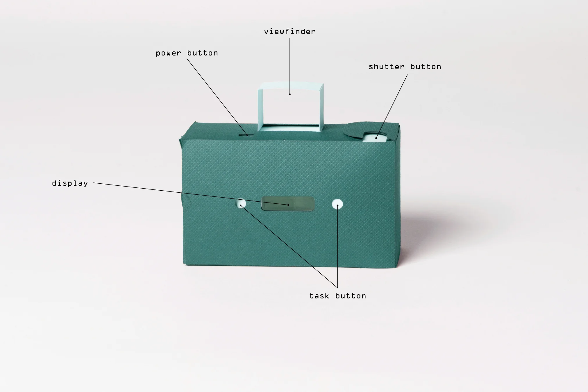
Turn camera on swiping the power button to the left. A red light flashes on backside and the display turns on
Select a task with the left and right button next to the display
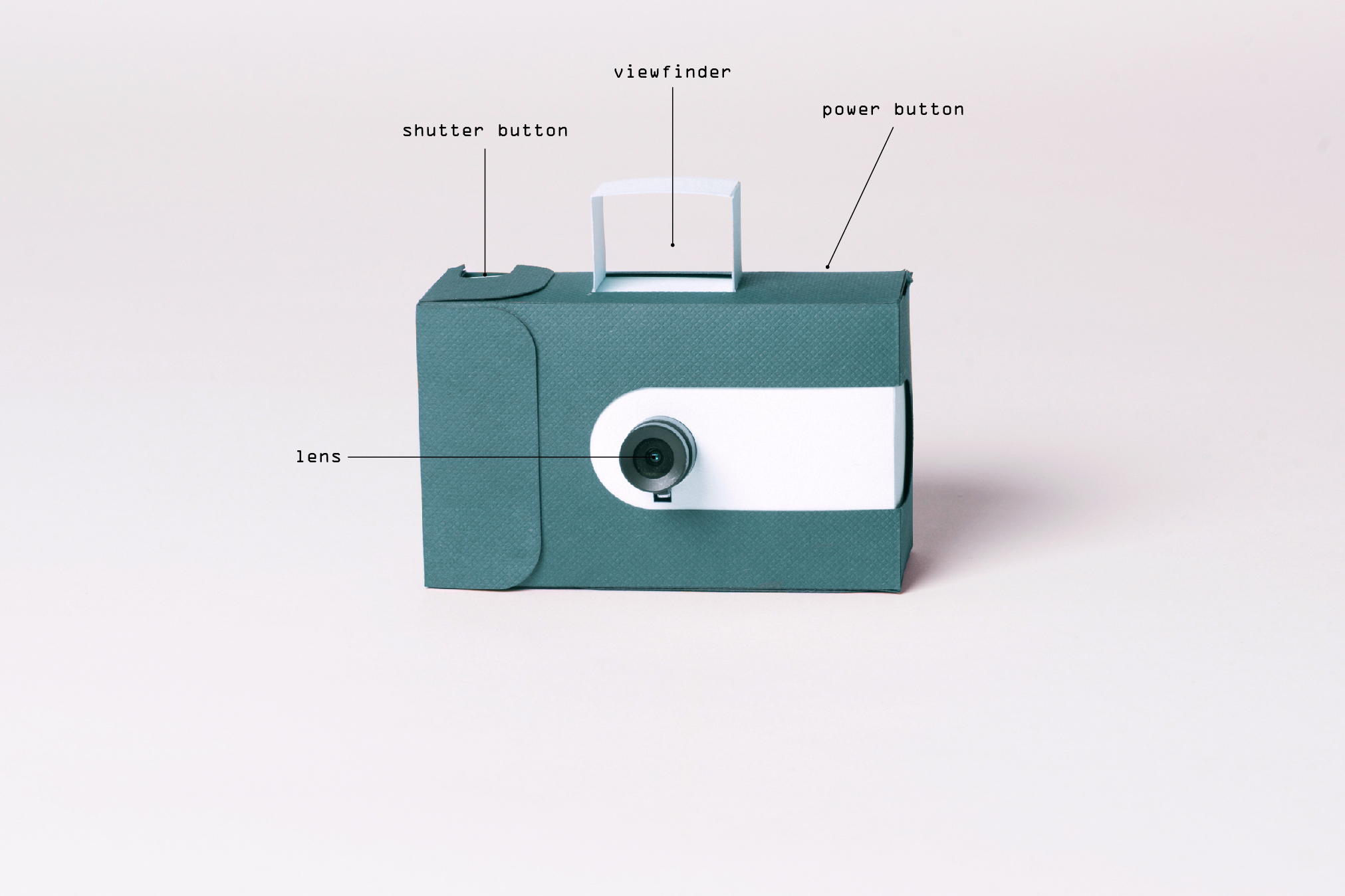
Use the viewfinder to frame your picture, press the shutter button to take a picture that answers the task. The display graphic changes when a picture is taken
Select your next task
Turn off after use